Software
GridDesign
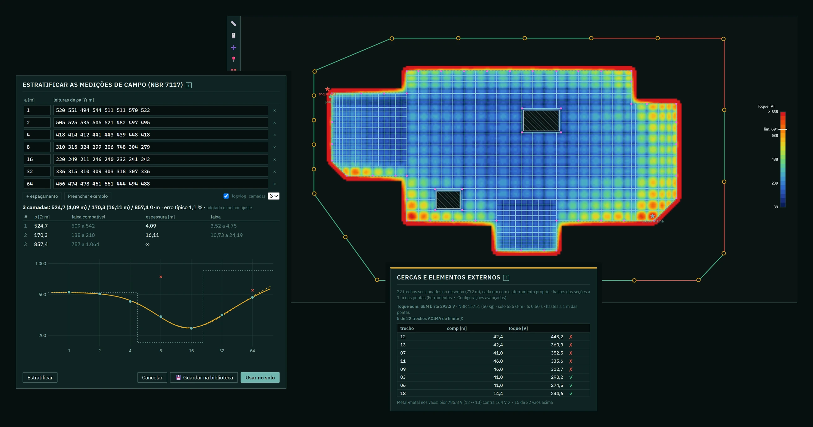
Substation grounding grids
From the grid drawing in DXF to the map of touch and step voltages, with soil stratification and fences checked section by section.
Inside the program
Outputs
ReportPDF with the results and the calculation log.
MethodologyPDF with the equations and stated assumptions.
DrawingDXF with the changes made on screen.
BIMRevit interoperability plugin (in development).
Standards
IEEE 80
The other three
01
BusRatingElectrical sizing of busbars
Ampacity, corona effect and short-circuit thermal withstand of bare overhead busbars. Preliminary mechanical validation of rigid busbars and insulators.IEEE 738 · CIGRE 207 · IEEE 605 · IEC 60865
02
BusForceLoads on flexible busbars
Loads on flexible busbars, to size the dead-end structures. With a BIM extension (Revit plugin).IEC 60865 · Overhead Power Lines (Kiessling)
03
SupForceLoads on equipment and supports
Loads on switchyard equipment, to define the design loads for the support structures.IEC 60865 · Overhead Power Lines (Kiessling)
See GridDesign run on a case of your own.
Book a call